Click Here For Character LCD Basics
Lcd Library
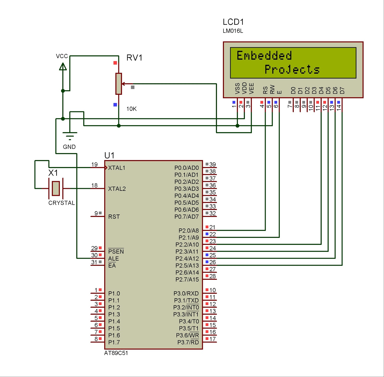
The mikroC PRO for 8051 provides a library for communication with Lcds (with HD44780 compliant controllers) through the 4-bit interface. An example of Lcd connections is given on the schematic at the bottom of this page.For creating a set of custom Lcd characters use Lcd Custom Character Tool.
External dependencies of Lcd Library
The following variables must be defined in all projects using Lcd Library : | Description : | Example : |
extern sfr sbit LCD_RS: | Register Select line. | sbit LCD_RS at P2_0_bit; |
extern sfr sbit LCD_EN: | Enable line. | sbit LCD_EN at P2_1_bit; |
extern sfr sbit LCD_D7; | Data 7 line. | sbit LCD_D7 at P2_5_bit; |
extern sfr sbit LCD_D6; | Data 6 line. | sbit LCD_D6 at P2_4_bit; |
extern sfr sbit LCD_D5; | Data 5 line. | sbit LCD_D5 at P2_3_bit; |
extern sfr sbit LCD_D4; | Data 4 line. | sbit LCD_D4 at P2_2_bit; |
Library Routines
Lcd_Init
Prototype | void Lcd_Init(); |
Returns | Nothing. |
Description | Initializes Lcd module. |
Requires | Global variables:
must be defined before using this function. |
Example | // lcd pinout settings sbit LCD_RS at P2_0_bit; sbit LCD_EN at P2_1_bit; sbit LCD_D7 at P2_5_bit; sbit LCD_D6 at P2_4_bit; sbit LCD_D5 at P2_3_bit; sbit LCD_D4 at P2_2_bit; ... Lcd_Init(); |
Lcd_Out
Prototype | void Lcd_Out(char row, char column, char *text); |
Returns | Nothing. |
Description | Prints text on Lcd starting from specified position. Both string variables and literals can be passed as a text. Parameters :
|
Requires | The Lcd module needs to be initialized. See Lcd_Init routine. |
Example | // Write text "Hello!" on Lcd starting from row 1, column 3: Lcd_Out(1, 3, "Hello!"); |
Lcd_Out_CP
Prototype | void Lcd_Out_Cp(char *text); |
Returns | Nothing. |
Description | Prints text on Lcd at current cursor position. Both string variables and literals can be passed as a text. Parameters :
|
Requires | The Lcd module needs to be initialized. See Lcd_Init routine. |
Example | // Write text "Here!" at current cursor position: Lcd_Out_CP("Here!"); |
Lcd_Chr
Prototype | void Lcd_Chr(char row, char column, char out_char); |
Returns | Nothing. |
Description | Prints character on Lcd at specified position. Both variables and literals can be passed as a character. Parameters :
|
Requires | The Lcd module needs to be initialized. See Lcd_Init routine. |
Example | // Write character "i" at row 2, column 3: Lcd_Chr(2, 3, 'i'); |
Lcd_Chr_CP
Prototype | void Lcd_Chr_Cp(char out_char); |
Returns | Nothing. |
Description | Prints character on Lcd at current cursor position. Both variables and literals can be passed as a character. Parameters :
|
Requires | The Lcd module needs to be initialized. See Lcd_Init routine. |
Example | // Write character "e" at current cursor position: Lcd_Chr_CP('e'); |
Lcd_Cmd
Prototype | void Lcd_Cmd(char out_char); |
Returns | Nothing. |
Description | Sends command to Lcd. Parameters :
|
Requires | The Lcd module needs to be initialized. See Lcd_Init table. |
Example | // Clear Lcd display: Lcd_Cmd(_LCD_CLEAR); |
Available Lcd Commands
Lcd Command | Purpose |
_LCD_FIRST_ROW | Move cursor to the 1st row |
_LCD_SECOND_ROW | Move cursor to the 2nd row |
_LCD_THIRD_ROW | Move cursor to the 3rd row |
_LCD_FOURTH_ROW | Move cursor to the 4th row |
_LCD_CLEAR | Clear display |
_LCD_RETURN_HOME | Return cursor to home position, returns a shifted display to its original position. Display data RAM is unaffected. |
_LCD_CURSOR_OFF | Turn off cursor |
_LCD_UNDERLINE_ON | Underline cursor on |
_LCD_BLINK_CURSOR_ON | Blink cursor on |
_LCD_MOVE_CURSOR_LEFT | Move cursor left without changing display data RAM |
_LCD_MOVE_CURSOR_RIGHT | Move cursor right without changing display data RAM |
_LCD_TURN_ON | Turn Lcd display on |
_LCD_TURN_OFF | Turn Lcd display off |
_LCD_SHIFT_LEFT | Shift display left without changing display data RAM |
_LCD_SHIFT_RIGHT | Shift display right without changing display data RAM |
Code
The following code demonstrates usage of the Lcd Library routines:// Lcd module connections
sbit LCD_RS at P2_0_bit;
sbit LCD_EN at P2_1_bit;
sbit LCD_D4 at P2_2_bit;
sbit LCD_D5 at P2_3_bit;
sbit LCD_D6 at P2_4_bit;
sbit LCD_D7 at P2_5_bit;
// End Lcd module connections
char txt1[] = "Embedded";
char txt2[] = "Projects";
char txt3[] = "Lcd 4 bit";
char txt4[] = "Tutorial";
char i; // Loop variable
void Move_Delay() { // Function used for text moving
Delay_ms(500); // You can change the moving speed here
}
void main(){
Lcd_Init(); // Initialize Lcd
Lcd_Cmd(_LCD_CLEAR); // Clear display
Lcd_Cmd(_LCD_CURSOR_OFF); // Cursor off
Lcd_Out(1,6,txt3); // Write text in first row
Lcd_Out(2,6,txt4); // Write text in second row
Delay_ms(2000);
Lcd_Cmd(_LCD_CLEAR); // Clear display
Lcd_Out(1,1,txt1); // Write text in first row
Lcd_Out(2,5,txt2); // Write text in second row
Delay_ms(2000);
// Moving text
for(i=0; i<4; i++) { // Move text to the right 4 times
Lcd_Cmd(_LCD_SHIFT_RIGHT);
Move_Delay();
}
while(1) { // Endless loop
for(i=0; i<8; i++) { // Move text to the left 7 times
Lcd_Cmd(_LCD_SHIFT_LEFT);
Move_Delay();
}
for(i=0; i<8; i++) { // Move text to the right 7 times
Lcd_Cmd(_LCD_SHIFT_RIGHT);
Move_Delay();
}
}
}
Circuit