Showing posts with label 8051. Show all posts

LCD based digital alarm clock using 89S51 microcontroller

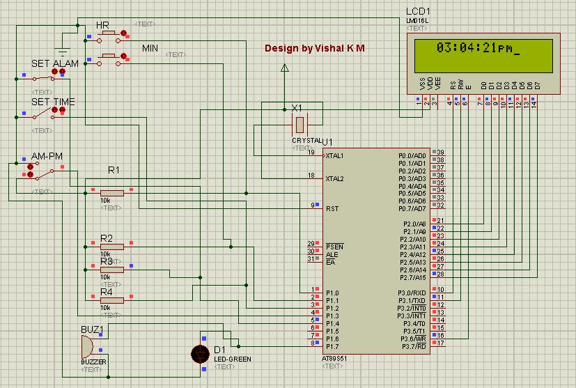
 Circuit Diagram
An alarm clock is a clock that indicates a pre-set time by producing sound at that time. This functionality of digital clock is used to awaken people or remind them of something. A digital clock is one that displays time digitally. The project explained here, displays time on a 16x2 LCD module. The LCD is interfaced with 8051 microcontroller (AT89S51). This circuit can be used in cars, houses, offices etc.

This clock works in 12 hour mode and is configured by programming the microcontroller AT89S51. The program uses a delay function for producing a delay of 1 second.
The connections in the circuit are as following: port P2 of microcontroller is used as data input port which is connected to data pins (7-14) of LCD. P3^0, P3^1 and P3^6 pins of microcontroller are connected to control pins RS, RW and EN of LCD. P1^0, P1^1, P1^2 and P1^3 pins of microcontroller are connected to tactile switches to take manual inputs.

On reset, the LCD prompts the user to set alarm. Only the hour and minute components can be set by pressing the corresponding switches, repeatedly. These switches are made active low and so they provide ground to the corresponding input pins of the microcontroller AT89S51. The AM/PM mode is set by toggling the switch between ground and Vcc. Ground would set the clock in AM mode while Vcc would set it in PM mode.


After that the LCD prompts the user to set time. Only the hour and minute components can be set by pressing the corresponding switches, repeatedly. These switches are made active low and so they provide ground to the corresponding input pins of the controller. The AM/PM mode is set by toggling the switch between ground and Vcc. Ground would set the clock in AM mode while Vcc would set it in PM mode. The clock starts when start pin is connected to Vcc by pressing the switch.

The set time is displayed on LCD screen and changes as the time passes on. Seconds are increased after every one second by making use of delay function. As second reaches 59, minute is incremented by one and second is reset to 0. Similarly, as minute reaches 59, hour is increased by one and minute is set to 0. After hour reaches 11, minute reaches 59 and second reaches 59, all of them are set to 0 and the AM/PM mode is changed accordingly.

When the clock time becomes equal to the alarm time, a message ‘Alarm’ is displayed on LCD and alarm pin of microcontroller goes high for some duration. This pin can be connected to a speaker or buzzer to sound the alarm at the pre-set time.

8051 4 Bit LCD Interfacing Tutorial


Click Here For Character LCD Basics


Lcd Library

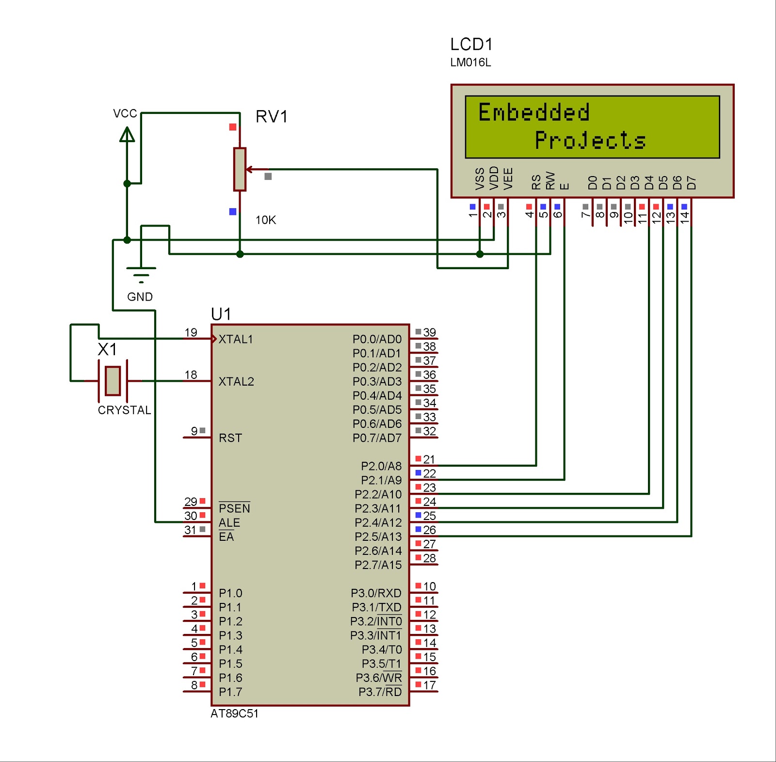
The mikroC PRO for 8051 provides a library for communication with Lcds (with HD44780 compliant controllers) through the 4-bit interface. An example of Lcd connections is given on the schematic at the bottom of this page.
For creating a set of custom Lcd characters use Lcd Custom Character Tool.

External dependencies of Lcd Library

The following variables must be defined in all projects using Lcd Library :
Description :
Example :
extern sfr sbit LCD_RS:
Register Select line.
sbit LCD_RS at P2_0_bit;
extern sfr sbit LCD_EN:
Enable line.
sbit LCD_EN at P2_1_bit;
extern sfr sbit LCD_D7;
Data 7 line.
sbit LCD_D7 at P2_5_bit;
extern sfr sbit LCD_D6;
Data 6 line.
sbit LCD_D6 at P2_4_bit;
extern sfr sbit LCD_D5;
Data 5 line.
sbit LCD_D5 at P2_3_bit;
extern sfr sbit LCD_D4;
Data 4 line.
sbit LCD_D4 at P2_2_bit;

Library Routines

Lcd_Init

Prototype
void Lcd_Init();
Returns
Nothing.
Description
Initializes Lcd module.
Requires
Global variables:
  • LCD_D7: data bit 7
  • LCD_D6: data bit 6
  • LCD_D5: data bit 5
  • LCD_D4: data bit 4
  • RS: register select (data/instruction) signal pin
  • EN: enable signal pin
must be defined before using this function.
Example
// lcd pinout settings
 
sbit LCD_RS at P2_0_bit;
sbit LCD_EN at P2_1_bit;
sbit LCD_D7 at P2_5_bit;
sbit LCD_D6 at P2_4_bit;
sbit LCD_D5 at P2_3_bit;
sbit LCD_D4 at P2_2_bit;
 
...
 
Lcd_Init();

Lcd_Out

Prototype
void Lcd_Out(char row, char column, char *text);
Returns
Nothing.
Description
Prints text on Lcd starting from specified position. Both string variables and literals can be passed as a text.
Parameters :
  • row: starting position row number
  • column: starting position column number
  • text: text to be written
Requires
The Lcd module needs to be initialized. See Lcd_Init routine.
Example
// Write text "Hello!" on Lcd starting from row 1, column 3:
Lcd_Out(1, 3, "Hello!");

Lcd_Out_CP

Prototype
void Lcd_Out_Cp(char *text);
Returns
Nothing.
Description
Prints text on Lcd at current cursor position. Both string variables and literals can be passed as a text.
Parameters :
  • text: text to be written
Requires
The Lcd module needs to be initialized. See Lcd_Init routine.
Example
// Write text "Here!" at current cursor position:
Lcd_Out_CP("Here!");

Lcd_Chr

Prototype
void Lcd_Chr(char row, char column, char out_char);
Returns
Nothing.
Description
Prints character on Lcd at specified position. Both variables and literals can be passed as a character.
Parameters :
  • row: writing position row number
  • column: writing position column number
  • out_char: character to be written
Requires
The Lcd module needs to be initialized. See Lcd_Init routine.
Example
// Write character "i" at row 2, column 3:
Lcd_Chr(2, 3, 'i');

Lcd_Chr_CP

Prototype
void Lcd_Chr_Cp(char out_char);
Returns
Nothing.
Description
Prints character on Lcd at current cursor position. Both variables and literals can be passed as a character.
Parameters :
  • out_char: character to be written
Requires
The Lcd module needs to be initialized. See Lcd_Init routine.
Example
// Write character "e" at current cursor position:
Lcd_Chr_CP('e');

Lcd_Cmd

Prototype
void Lcd_Cmd(char out_char);
Returns
Nothing.
Description
Sends command to Lcd.
Parameters :
  • out_char: command to be sent
Note: Predefined constants can be passed to the function, see Available Lcd Commands.
Requires
The Lcd module needs to be initialized. See Lcd_Init table.
Example
// Clear Lcd display:
Lcd_Cmd(_LCD_CLEAR);

Available Lcd Commands

Lcd Command
Purpose
_LCD_FIRST_ROW
Move cursor to the 1st row
_LCD_SECOND_ROW
Move cursor to the 2nd row
_LCD_THIRD_ROW
Move cursor to the 3rd row
_LCD_FOURTH_ROW
Move cursor to the 4th row
_LCD_CLEAR
Clear display
_LCD_RETURN_HOME
Return cursor to home position, returns a shifted display to its original position. Display data RAM is unaffected.
_LCD_CURSOR_OFF
Turn off cursor
_LCD_UNDERLINE_ON
Underline cursor on
_LCD_BLINK_CURSOR_ON
Blink cursor on
_LCD_MOVE_CURSOR_LEFT
Move cursor left without changing display data RAM
_LCD_MOVE_CURSOR_RIGHT
Move cursor right without changing display data RAM
_LCD_TURN_ON
Turn Lcd display on
_LCD_TURN_OFF
Turn Lcd display off
_LCD_SHIFT_LEFT
Shift display left without changing display data RAM
_LCD_SHIFT_RIGHT
Shift display right without changing display data RAM

Code

The following code demonstrates usage of the Lcd Library routines:


// Lcd module connections
sbit LCD_RS at P2_0_bit;
sbit LCD_EN at P2_1_bit;

sbit LCD_D4 at P2_2_bit;
sbit LCD_D5 at P2_3_bit;
sbit LCD_D6 at P2_4_bit;
sbit LCD_D7 at P2_5_bit;
// End Lcd module connections

char txt1[] = "Embedded";
char txt2[] = "Projects";
char txt3[] = "Lcd 4 bit";
char txt4[] = "Tutorial";

char i;                              // Loop variable

void Move_Delay() {                  // Function used for text moving
  Delay_ms(500);                     // You can change the moving speed here
}

void main(){

  Lcd_Init();                        // Initialize Lcd

  Lcd_Cmd(_LCD_CLEAR);               // Clear display
  Lcd_Cmd(_LCD_CURSOR_OFF);          // Cursor off
  Lcd_Out(1,6,txt3);                 // Write text in first row

  Lcd_Out(2,6,txt4);                 // Write text in second row
  Delay_ms(2000);
  Lcd_Cmd(_LCD_CLEAR);               // Clear display

  Lcd_Out(1,1,txt1);                 // Write text in first row
  Lcd_Out(2,5,txt2);                 // Write text in second row

  Delay_ms(2000);

  // Moving text
  for(i=0; i<4; i++) {               // Move text to the right 4 times
    Lcd_Cmd(_LCD_SHIFT_RIGHT);
    Move_Delay();
  }

  while(1) {                         // Endless loop
    for(i=0; i<8; i++) {             // Move text to the left 7 times
      Lcd_Cmd(_LCD_SHIFT_LEFT);
      Move_Delay();
    }

    for(i=0; i<8; i++) {             // Move text to the right 7 times
      Lcd_Cmd(_LCD_SHIFT_RIGHT);
      Move_Delay();
    }
  }
}


Circuit


8051 Serial Communication Tutorial (UART)


First, a quick history of RS232. What is RS232? It's just a name for a standard that has propagated from generation to generation of computers. The first computers had serial ports that used RS232, and even current computers have serial ports (or at least USB ports that act like RS232 ports). Back in the day, serial information needed to be passed from devices like printers, joysticks, scanners, etc to the computer. The simplest way to do this was to pass a series of 1s and 0s to the computer. Both the computer and the device agreed on a speed of information - 'bits per second'. A computer would pass image data to a printer at 9600 bits per second and the printer would listen for this stream of 1s and 0s expecting a new bit every 1/9600 = 104us (104 micro-seconds, 0.000104 seconds). As long as the computer output bits at the pre-determined speed, the printer could listen.
Zoom forward to today. Electronics have changed a bit. Before they were relatively high power, high voltage devices. The standard that is 'RS232' dictates that a bit ranges from -12V to +12V. Modern electronics do not operate at such high positive and negative voltages. In fact, our 8051  runs 0V to 5V. So how do we get our 5V micro to talk the RS232 +/-12V voltages? This problem has been solved by the IC manufacturers of the world. They have made an IC that is generically known as the MAX232 (very close to RS232, no?).
The MAX232 is an IC originally designed by a company called Maxim IC that converts the +/-12V signals of RS232 down to the 0/5V signals that our 8051  can understand. It also boosts the voltage of our 8051  to the needed +/-12V of the RS232 protocol so that a computer can understand our 8051  and vice versa. To get our 8051  IC sending serial characters to a computer, we have to send these serial signals through a MAX232 circuit so that the computer receives +/-12V RS232 signals. Don't worry if you're working with a chip labeled 'ICL232' or 'ST232' - these are just generics of the MAX232. Everyone says 'MAX232'. The ICs all function the same and nearly all have the same pinout.


UART Library
The UART hardware module is available with a number of 8051 compliant MCUs. The mikroC PRO for 8051 UART Library provides comfortable work with the Asynchronous (full duplex) mode.
Library Routines
Notes:
  • UART routines require you to specify the module you want to use. To select the desired UART, simply change the letter x in the prototype for a number from 1 to 2.
    Number of UART modules per MCU differs from chip to chip. Please, read the appropriate datasheet before utilizing this library.
Example: UART2_Init(9600); initializes UART 2 module at 9600 bps.
  • Some MCUs have multiple UART modules. Switching between the UART modules in the UART library is done by the UART_Set_Active function (UART module has to be previously initialized).
  • Some of the MCUs do not support UARTx_Init_Advanced routine. Please, refer to the appropriate datasheet.
UARTx_Init
Prototype
void UARTx_Init(unsigned long baud_rate);
Returns
Nothing.
Description
Configures and initializes the UART module.
The internal UART module module is set to:
  • receiver enabled
  • frame size 8 bits
  • 1 STOP bit
  • parity mode disabled
  • disabled automatic address recognition
Parameters :
  • baud_rate: requested baud rate
Refer to the device datasheet for baud rates allowed for specific Fosc.
Requires
MCU with the UART module.
Example
// Initialize hardware UART1 and establish communication at 9600 bps
UART1_Init(9600);
UARTx_Init_Advanced
Prototype
void UARTx_Init_Advanced(unsigned long baud_rate, char adv_setting);
Returns
Nothing.
Description
Configures and initializes UART module.
Parameters :
  • baud_rate sets the desired UART baud rate
  • adv_setting: UART module configuration flags. Predefined library constants (see the table below) can be ORed to form appropriate configuration value.
Description
Predefined library const
Parity constants:
Parity mode disabled
_UART_NOPARITY
Even parity
_UART_EVENPARITY
Odd parity
_UART_ODDPARITY
Mark parity
_UART_MARKPARITY
Space parity
_UART_SPACEPARITY
Stop bit constants:
1 stop bit
_UART_ONE_STOPBIT
2 stop bits
_UART_TWO_STOPBITS
Output mode constants:
Output set as quasi-bidirectional (8051)
_UART_OUTPUT_8051
Output set as push-pull
_UART_OUTPUT_PUSH_PULL
Output set as open-drain
_UART_OUTPUT_OPEN_DRAIN
Notes:
  • Some MCUs do not support advanced configuration of the UART module. Please consult appropriate datasheet.
  • Advanced parity and stop bit settings are supported by some Silicon Laboratories MCU's, while output settings by some ATMEL MCU's. Please, consult appropriate datasheet before using UARTx_Init_Advanced routine.
Requires
MCU must have UART module.
Example
// Initialize hardware UART1 module and establish communication at 9600 bps, 8-bit data, even parity and 2 STOP bits
UART1_Init_Advanced(9600, _UART_EVENPARITY, _UART_TWO_STOPBITS);
UARTx_Data_Ready
Prototype
char UARTx_Data_Ready();
Returns
  • 1 if data is ready for reading
  • 0 if there is no data in the receive register
Description
Use the function to test if data in receive buffer is ready for reading.
Requires
MCU with the UART module.
The UART module must be initialized before using this routine. See UARTx_Init and UARTx_Init_Advanced routines.
Example
char receive;
...
// read data if ready
if (UART1_Data_Ready())
  receive = UART1_Read();
UARTx_Read
Prototype
char UARTx_Read();
Returns
Returns the received byte.
Description
The function receives a byte via UART. Use the UARTx_Data_Ready function to test if data is ready first.
Requires
MCU with the UART module.
The UART module must be initialized before using this routine. See UARTx_Init and UARTx_Init_Advanced routines.
Example
char receive;
...
// read data if ready
if (UART1_Data_Ready())
  receive = UART1_Read();
UARTx_Read_Text
Prototype
void UARTx_Read_Text(char *Output, char *Delimiter, char Attempts);
Returns
Nothing.
Description
Reads characters received via UART until the delimiter sequence is detected. The read sequence is stored in the parameter output; delimiter sequence is stored in the parameter delimiter.
This is a blocking call: the delimiter sequence is expected, otherwise the procedure exits (if the delimiter is not found).
Parameters :
  • Output: received text
  • Delimiter: sequence of characters that identifies the end of a received string
  • Attempts: defines number of received characters in which Delimiter sequence is expected. If Attempts is set to 255, this routine will continuously try to detect the Delimiter sequence.
Requires
UART HW module must be initialized and communication established before using this function. See UARTx_Init and UARTx_Init_Advanced routines.
Example
Read text until the sequence “OK” is received, and send back what’s been received:
UART1_Init(4800);                          // initialize UART1 module
Delay_ms(100);

 while (1) {
   if (UART1_Data_Ready() == 1) {          // if data is received
     UART1_Read_Text(output, "OK", 10); // reads text until 'OK' is found
     UART1_Write_Text(output);             // sends back text
 }
}
UARTx_Write
Prototype
void UARTx_Write(char _data);
Returns
Nothing.
Description
The function transmits a byte via the UART module.
Parameters :
  • _data: data to be sent
Requires
MCU with the UART module.
The UART module must be initialized before using this routine. See UARTx_Init and UARTx_Init_Advanced routines.
Example
unsigned char _data = 0x1E;
...
UART1_Write(_data);
UARTx_Write_Text
Prototype
void UARTx_Write_Text(char * UART_text);
Returns
Nothing.
Description
Sends text via UART. Text should be zero terminated.
Parameters :
  • UART_text: text to be sent
Requires
UART HW module must be initialized and communication established before using this function. See UARTx_Init and UARTx_Init_Advanced routines.
Example
Read text until the sequence “OK” is received, and send back what’s been received:
UART1_Init(4800);                          // initialize UART1 module
Delay_ms(100);

 while (1) {
   if (UART1_Data_Ready() == 1) {          // if data is received
     UART1_Read_Text(output, "OK", 10); // reads text until 'OK' is found
     UART1_Write_Text(output);             // sends back text
 }
}
UART_Set_Active
Prototype
void UART_Set_Active(char (*read_ptr)(), void (*write_ptr)(unsigned char data_), char (*ready_ptr)())
Returns
Nothing.
Description
Sets active UART module which will be used by the UART library routines.
Parameters :
Requires
Routine is available only for MCUs with two UART modules.
Used UART module must be initialized before using this routine. See UARTx_Init and UARTx_Init_Advanced routines.
Example
// Activate UART2 module
UART_Set_Active(&UART2_Read, &UART2_Write, &UART2_Data_Ready);
Library Example
This example demonstrates simple data exchange via UART. If MCU is connected to the PC, you can test the example from the mikroC PRO for 8051 USART Terminal.
char uart_rd;

void main() {
 
  UART1_Init(4800);               // Initialize UART module at 4800 bps
  Delay_ms(100);                  // Wait for UART module to stabilize
 
  UART1_Write_Text("Start");
  while (1) {                     // Endless loop
    if (UART1_Data_Ready()) {     // If data is received,
      uart_rd = UART1_Read();     //   read the received data,
      UART1_Write(uart_rd);       //   and send data via UART
    }
  }
}


HW Connection

 
Copyright Electronics Projects And Details All Rights Reserved
ProSense theme created by Dosh Dosh and The Wrong Advices.
Blogerized by Alat Recording Studio Rekaman.