Showing posts with label Embedded System. Show all posts

Led Blinking using Experiment 12F629


Program

//////////////////////////////////////////////////////////////////////
void init_ports(void) {
TRISIO = 0;
}
//////////////////////////////////////////////////////////////////////
void main()
{
int x;
init_ports();
do{
GPIO.GP1=1;
Delay_ms(1000);

GPIO.GP1=0;
Delay_ms(1000);
//GPIO.GP1=1;
}while(1);

}
Code is written using MikroC


LCD based digital alarm clock using 89S51 microcontroller

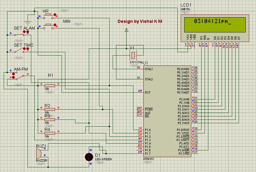
 Circuit Diagram
An alarm clock is a clock that indicates a pre-set time by producing sound at that time. This functionality of digital clock is used to awaken people or remind them of something. A digital clock is one that displays time digitally. The project explained here, displays time on a 16x2 LCD module. The LCD is interfaced with 8051 microcontroller (AT89S51). This circuit can be used in cars, houses, offices etc.

This clock works in 12 hour mode and is configured by programming the microcontroller AT89S51. The program uses a delay function for producing a delay of 1 second.
The connections in the circuit are as following: port P2 of microcontroller is used as data input port which is connected to data pins (7-14) of LCD. P3^0, P3^1 and P3^6 pins of microcontroller are connected to control pins RS, RW and EN of LCD. P1^0, P1^1, P1^2 and P1^3 pins of microcontroller are connected to tactile switches to take manual inputs.

On reset, the LCD prompts the user to set alarm. Only the hour and minute components can be set by pressing the corresponding switches, repeatedly. These switches are made active low and so they provide ground to the corresponding input pins of the microcontroller AT89S51. The AM/PM mode is set by toggling the switch between ground and Vcc. Ground would set the clock in AM mode while Vcc would set it in PM mode.


After that the LCD prompts the user to set time. Only the hour and minute components can be set by pressing the corresponding switches, repeatedly. These switches are made active low and so they provide ground to the corresponding input pins of the controller. The AM/PM mode is set by toggling the switch between ground and Vcc. Ground would set the clock in AM mode while Vcc would set it in PM mode. The clock starts when start pin is connected to Vcc by pressing the switch.

The set time is displayed on LCD screen and changes as the time passes on. Seconds are increased after every one second by making use of delay function. As second reaches 59, minute is incremented by one and second is reset to 0. Similarly, as minute reaches 59, hour is increased by one and minute is set to 0. After hour reaches 11, minute reaches 59 and second reaches 59, all of them are set to 0 and the AM/PM mode is changed accordingly.

When the clock time becomes equal to the alarm time, a message ‘Alarm’ is displayed on LCD and alarm pin of microcontroller goes high for some duration. This pin can be connected to a speaker or buzzer to sound the alarm at the pre-set time.

PIC Countdown Timer (0-99)


This project describes how to program PIC16F628A to function as a 00-99 min programmable timer. User can set any time between 00-99 minutes and can turn ON a device for that period. The device will be automatically turned OFF after the time expires. For demonstration, the ON/OFF condition of device is simulated by switching LED ON and OFF. With the use of three input switches (unit, ten, start/stop) the user can set ON time of the timer and can also control Start/Stop operation. The two time set switches are for selecting unit and tens digit of minute time interval (00-99). Once you set the value of minute interval, pressing the Start/Stop will turn the timer ON (LED will glow), and pressing the same button again at any point of time during timer operation will interrupt the process (LED will turn OFF) and the timer will be reset. LCD display will provide timer status and user interface for setting time.


Circuit


Code
Compiled using MikroC for PIC


/*
  ############################################


  MCU:16F628A
  Project: PIC Countdown Timer (0-99)
  Vishal K M
  Jan 10, 2012
  ############################################

 
*/

// LCD module connections
sbit LCD_RS at RA0_bit;
sbit LCD_EN at RA1_bit;
sbit LCD_D4 at RB4_bit;
sbit LCD_D5 at RB5_bit;
sbit LCD_D6 at RB6_bit;
sbit LCD_D7 at RB7_bit;
sbit LCD_RS_Direction at TRISA0_bit;
sbit LCD_EN_Direction at TRISA1_bit;
sbit LCD_D4_Direction at TRISB4_bit;
sbit LCD_D5_Direction at TRISB5_bit;
sbit LCD_D6_Direction at TRISB6_bit;
sbit LCD_D7_Direction at TRISB7_bit;
// End LCD module connections

// Tact switches and Relay ports
sbit Relay at RA3_bit;
sbit SS_Select at RB0_bit;    // Start Stop Timer Select
sbit Unit_Button at RB1_bit;  // Set unit min
sbit Ten_Button at RB2_bit;   // Set ten min


// Messages
char Message1[]="Timer by VISHAL";
char Message2[]="Device ON";
char Message3[]="Device OFF";
char Message4[]="Set Time:    min";
char Message5[]="Time Left:   min";
unsigned short i, j, unit=0, ten=0, ON_OFF=0, index=0, clear, time;
char *digit = "00";
// 300ms Delay
void Delay_300(){
 Delay_ms(300);
}

void Display_Digits(){
 digit[1]=unit+48;
 digit[0]=ten+48;
 Lcd_Out(2,11,digit);
}

void start_timer(unsigned short MinVal){
 unsigned short temp1, temp2;
 Relay = 1;
 ON_OFF = 1;
 Lcd_Cmd(_LCD_CLEAR);
 Lcd_Out(1,1,Message2);
 Lcd_Out(2,1,Message5);
 OPTION_REG = 0x80 ;
 INTCON = 0x90;
 for (i=0; i<MinVal; i++){
  temp1 = (MinVal-i)%10 ;
  temp2 = (MinVal-i)/10 ;
  Lcd_Chr(2, 12, temp2+48);
  Lcd_Chr(2, 13, temp1+48);
  j=1;
  do {
  Delay_ms(1000);
  j++;
  } while(((j<=60) && (Clear ==0)));
  if (Clear) {
   Relay = 0;
   Delay_ms(500);
   Lcd_Out(1,1,Message3);
   INTCON = 0x00;
   goto stop;
   }
 }
 stop:
 Relay = 0;
 ON_OFF = 0;
 unit = 0;
 ten = 0;
 clear = 1;
}

void interrupt(void){
  if (INTCON.INTF == 1)   // Check if INTF flag is set
   {
    Clear = 1;
    INTCON.INTF = 0;       // Clear interrupt flag before exiting ISR
   }
  }

void main() {
  CMCON  |= 7;                       // Disable Comparators
  TRISB = 0b00001111;
  TRISA = 0b11110000;
  Relay = 0;

  Lcd_Init();                        // Initialize LCD
 start:
  clear = 0;
  Lcd_Cmd(_LCD_CLEAR);               // Clear display
  Lcd_Cmd(_LCD_CURSOR_OFF);          // Cursor off
  Lcd_Out(1,1,Message1);
  Lcd_Out(2,1,Message4);
  Display_Digits()  ;
 do {

     if(!Unit_Button){
     Delay_300();
     unit ++;
     if(unit==10) unit=0;
     Display_Digits();
    } // If !Unit_Button

    if(!Ten_Button){
     Delay_300();
     ten ++;
     if(ten==10) ten=0;
     Display_Digits();
    } // If !Ten_Button

    if(!SS_Select){
     Delay_300();
     time = ten*10+unit ;
     if(time > 0) start_timer(time);
    } // If !SS_Select

    if(clear){
     goto start;
    }
   } while(1);
}


Facebook page 

PIC 4 Bit LCD Interfacing Tutorial

The mikroC PRO for PIC provides a library for communication with Lcds (with HD44780 compliant controllers) through the 4-bit interface. An example of Lcd connections is given on the schematic at the bottom of this page.

For LCD Basics: Character LCD Basics  

External dependencies of Lcd Library


The following variables must be defined in all projects using Lcd Library :
Description :
Example :
extern sfr sbit LCD_RS:
Register Select line.
sbit LCD_RS at RB4_bit;
extern sfr sbit LCD_EN:
Enable line.
sbit LCD_EN at RB5_bit;
extern sfr sbit LCD_D7;
Data 7 line.
sbit LCD_D7 at RB3_bit;
extern sfr sbit LCD_D6;
Data 6 line.
sbit LCD_D6 at RB2_bit;
extern sfr sbit LCD_D5;
Data 5 line.
sbit LCD_D5 at RB1_bit;
extern sfr sbit LCD_D4;
Data 4 line.
sbit LCD_D4 at RB0_bit;
extern sfr sbit LCD_RS_Direction;
Register Select direction pin.
sbit LCD_RS_Direction at TRISB4_bit;
extern sfr sbit LCD_EN_Direction;
Enable direction pin.
sbit LCD_EN_Direction at TRISB5_bit;
extern sfr sbit LCD_D7_Direction;
Data 7 direction pin.
sbit LCD_D7_Direction at TRISB3_bit;
extern sfr sbit LCD_D6_Direction;
Data 6 direction pin.
sbit LCD_D6_Direction at TRISB2_bit;
extern sfr sbit LCD_D5_Direction;
Data 5 direction pin.
sbit LCD_D5_Direction at TRISB1_bit;
extern sfr sbit LCD_D4_Direction;
Data 4 direction pin.
sbit LCD_D4_Direction at TRISB0_bit;
Library Routines
  • Lcd_Init

  • Lcd_Out

  • Lcd_Out_Cp

  • Lcd_Chr

  • Lcd_Chr_Cp

  • Lcd_Cmd
Lcd_Init


Prototype
void Lcd_Init();
Returns
Nothing.
Description
Initializes Lcd module.
Requires
Global variables:
  • LCD_D7: Data bit 7

  • LCD_D6: Data bit 6

  • LCD_D5: Data bit 5

  • LCD_D4: Data bit 4

  • LCD_RS: Register Select (data/instruction) signal pin

  • LCD_EN: Enable signal pin

  • LCD_D7_Direction: Direction of the Data 7 pin

  • LCD_D6_Direction: Direction of the Data 6 pin

  • LCD_D5_Direction: Direction of the Data 5 pin

  • LCD_D4_Direction: Direction of the Data 4 pin

  • LCD_RS_Direction: Direction of the Register Select pin

  • LCD_EN_Direction: Direction of the Enable signal pin
must be defined before using this function.
Example
// Lcd pinout settings
sbit LCD_RS at RB4_bit;
sbit LCD_EN at RB5_bit;
sbit LCD_D7 at RB3_bit;
sbit LCD_D6 at RB2_bit;
sbit LCD_D5 at RB1_bit;
sbit LCD_D4 at RB0_bit;

// Pin direction
sbit LCD_RS_Direction at TRISB4_bit;
sbit LCD_EN_Direction at TRISB5_bit;
sbit LCD_D7_Direction at TRISB3_bit;
sbit LCD_D6_Direction at TRISB2_bit;
sbit LCD_D5_Direction at TRISB1_bit;
sbit LCD_D4_Direction at TRISB0_bit;
...

Lcd_Init();
Lcd_Out


Prototype
void Lcd_Out(char row, char column, char *text);
Returns
Nothing.
Description
Prints text on Lcd starting from specified position. Both string variables and literals can be passed as a text.
Parameters :
  • row: starting position row number

  • column: starting position column number

  • text: text to be written
Requires
The Lcd module needs to be initialized. See Lcd_Init routine.
Example
// Write text "Hello!" on Lcd starting from row 1, column 3:
Lcd_Out(1, 3, "Hello!");
Lcd_Out_Cp


Prototype
void Lcd_Out_Cp(char *text);
Returns
Nothing.
Description
Prints text on Lcd at current cursor position. Both string variables and literals can be passed as a text.
Parameters :
  • text: text to be written
Requires
The Lcd module needs to be initialized. See Lcd_Init routine.
Example
// Write text "Here!" at current cursor position:
Lcd_Out_Cp("Here!");
Lcd_Chr


Prototype
void Lcd_Chr(char row, char column, char out_char);
Returns
Nothing.
Description
Prints character on Lcd at specified position. Both variables and literals can be passed as a character.
Parameters :
  • row: writing position row number

  • column: writing position column number

  • out_char: character to be written
Requires
The Lcd module needs to be initialized. See Lcd_Init routine.
Example
// Write character "i" at row 2, column 3:
Lcd_Chr(2, 3, 'i');
Lcd_Chr_Cp


Prototype
void Lcd_Chr_Cp(char out_char);
Returns
Nothing.
Description
Prints character on Lcd at current cursor position. Both variables and literals can be passed as a character.
Parameters :
  • out_char: character to be written
Requires
The Lcd module needs to be initialized. See Lcd_Init routine.
Example
// Write character "e" at current cursor position:
Lcd_Chr_Cp('e');
Lcd_Cmd


Prototype
void Lcd_Cmd(char out_char);
Returns
Nothing.
Description
Sends command to Lcd.
Parameters :
  • out_char: command to be sent
  Note : Predefined constants can be passed to the function, see Available Lcd Commands.
Requires
The Lcd module needs to be initialized. See Lcd_Init table.
Example
// Clear Lcd display:
Lcd_Cmd(_LCD_CLEAR);
Available Lcd Commands


Lcd Command
Purpose
_LCD_FIRST_ROW
Move cursor to the 1st row
_LCD_SECOND_ROW
Move cursor to the 2nd row
_LCD_THIRD_ROW
Move cursor to the 3rd row
_LCD_FOURTH_ROW
Move cursor to the 4th row
_LCD_CLEAR
Clear display
_LCD_RETURN_HOME
Return cursor to home position, returns a shifted display to its original position. Display data RAM is unaffected.
_LCD_CURSOR_OFF
Turn off cursor
_LCD_UNDERLINE_ON
Underline cursor on
_LCD_BLINK_CURSOR_ON
Blink cursor on
_LCD_MOVE_CURSOR_LEFT
Move cursor left without changing display data RAM
_LCD_MOVE_CURSOR_RIGHT
Move cursor right without changing display data RAM
_LCD_TURN_ON
Turn Lcd display on
_LCD_TURN_OFF
Turn Lcd display off
_LCD_SHIFT_LEFT
Shift display left without changing display data RAM
_LCD_SHIFT_RIGHT
Shift display right without changing display data RAM
Code
// LCD module connections
sbit LCD_RS at RB4_bit;
sbit LCD_EN at RB5_bit;
sbit LCD_D4 at RB0_bit;
sbit LCD_D5 at RB1_bit;
sbit LCD_D6 at RB2_bit;
sbit LCD_D7 at RB3_bit;

sbit LCD_RS_Direction at TRISB4_bit;
sbit LCD_EN_Direction at TRISB5_bit;
sbit LCD_D4_Direction at TRISB0_bit;
sbit LCD_D5_Direction at TRISB1_bit;
sbit LCD_D6_Direction at TRISB2_bit;
sbit LCD_D7_Direction at TRISB3_bit;
// End LCD module connections

char txt1[] = "Embedded";   
char txt2[] = "Projects";
char txt3[] = "Lcd 4 bit";
char txt4[] = "Example";

char i;                              // Loop variable

void Move_Delay() {                  // Function used for text moving
  Delay_ms(500);                     // You can change the moving speed here
}

void main(){
 

  Lcd_Init();                        // Initialize LCD

  Lcd_Cmd(_LCD_CLEAR);               // Clear display
  Lcd_Cmd(_LCD_CURSOR_OFF);          // Cursor off
  Lcd_Out(1,6,txt3);                 // Write text in first row

  Lcd_Out(2,6,txt4);                 // Write text in second row
  Delay_ms(2000);
  Lcd_Cmd(_LCD_CLEAR);               // Clear display

  Lcd_Out(1,1,txt1);                 // Write text in first row
  Lcd_Out(2,5,txt2);                 // Write text in second row

  Delay_ms(2000);

  // Moving text
  for(i=0; i<4; i++) {               // Move text to the right 4 times
    Lcd_Cmd(_LCD_SHIFT_RIGHT);
    Move_Delay();
  }

  while(1) {                         // Endless loop
    for(i=0; i<8; i++) {             // Move text to the left 7 times
      Lcd_Cmd(_LCD_SHIFT_LEFT);
      Move_Delay();
    }

    for(i=0; i<8; i++) {             // Move text to the right 7 times
      Lcd_Cmd(_LCD_SHIFT_RIGHT);
      Move_Delay();
    }
  }
}

8051 programmer kit


All the student's may not properly works on microcontroller because  shortage of programmer kit(burner kit) whatever the  problem they have ,so now you can make your own programmer kit for 8051 microcontroller and can make more practical application and learn more efficiently in this field.For making the programmer kit we make the circuit step by step.
FOR P89V51RD2 microcontroller


Power Supply


  • Power supply 

  • DB9 connector

  • Line driver circuit

  • 8051 

  • final circuit of Programmer kit


1.  POWER SUPPLY: Before making any circuit we need to design its power supply it consist of many part like step down, ac-dc conversion, voltage stabilizing etc but we will giving the power to our board from an 12-volt adapter so our power supply consist of a voltage regulator,capacitor,diode, led and connector. 


    7805 voltage regulator


    • 7805:-It is the voltage regulator ic as pin diagram is shown.

    • diode IN4007 and the silver line part is its negative.

    • resistor R1=330ohm or we can also use 470ohm because it is use with the led.

    • A 2 pin male connector is required for giving the power to the circuit the +ve will connect with 1 pin of 7805.

    • A 1000uf capacitor is also use with power supply to reducing the ripple or maintaining the continuity.

    • Led:-the cutted portion of the led is negative.


2.  DB9 CONNECTOR: DB9 connector is use to connect the computer with your  programmer board it uses the RS232 cable to connect the DB9 port has 9 pins each pin has its own function but we will use only pin no 2 , 3 and  5.


  • pin no 2 is known as recieved data bit when controller transmit the data bit then computer recive from this pin. This is connected to the 14th pin of max232.

  • pin no 3 is named as transmit data the data will transmit form the computer with the help of this pin and this is connected 13th pin of max232.

  • pin no 5 we make this pin normally ground.


3.  LINE DRIVER CIRCUIT: The MAX232 is an Integrated Circuit that convert signal from an RS232 serial port to signal suitable for use in ttl compaitable digital logic circuits.The MAX232 is a dual driver/receiver and typically converts the RX, TX, CTS and RTS signals.For more details of MAX232 you can download the datasheet of it form here. download  


  • here the values of all the capacitors are 0.1 uf.

  • 16 pin is vcc should be maintained at 5volt dc.

  • the 15th pin becomes ground.

  • T1out-pin is use to send the data serially to the computer.

  • R1in-pin is use to recieve the data from the computer serially.

  • T1in-pin is use to tramsmitt the data from microcontroller to MAX232 which is actually going to computer.

  • R1out-pin is use for send the incoming data from MAX232 to microcontroller which is actually come from computer.

  • Download the MAX232 datasheet here.download 

4.  8051: The basic 8051 circuit consist of reset circuitry and oscillator circuit but before this we will look the pin diagram of the 8051 that how or what pin's we are using to make our circuit.


8051 microcontroller


As we can see in the fig next that the 8051 microcontroller has 40 pin it has 32 pin I/O lines or we can 32 input and output lines .It consist of four 8bit port's thats why we call it 8bit microcontroller. For our circuit we only need 8 pins these are as follow.


  • We need a 40 pin IC base

  • RST this is the pin  no 9 called as reset pin this pin reset the program counter 0f 8051 microcontroller and it is active high.

  • XTAL1 and XTAL2 are for providing the oscillations to the controller.

  • 10 and 11th pin are use for serial communication.

  • 40th and 31st is to provide vcc basically set at 5volt.

  • 20th pin is become ground.

*The two basic circuit for 8051 microcontroller are listed below.


reset circuit


XTAL connection to8051

4.  FINAL PROGRAMMER CIRCUIT: When we connect the all small circuit with each other than the programmer circuit is in front of you and it is like below.


Copyright Electronics Projects And Details All Rights Reserved
ProSense theme created by Dosh Dosh and The Wrong Advices.
Blogerized by Alat Recording Studio Rekaman.